Inveterate meddling #378: Quick notes on using 3-Pin Voltage regulators, Part 2
Noise feed-through
Recent discussions in the PFM Forum DIY room have revisited the subject of adapting cheap switch-mode power supplies for audio purposes. Now, I think results will depend on exactly how you implement things, but there's certainly no intrinsic reason why SMPS can't be useful or even very, very good. After all, apart from their usually poor transient response - not a big problem in a raw supply with post regulation - they have no gross ripple in the audioband. That's got to be a good thing. And given the efficiency and small size - at least when compared with the usual 'audiophool-overkill' of massively overrated linear supplies - SMPS do offer an elegant solution. That said, there ain't no free lunch. SMPS are noisy, and in a way which can be difficult to deal with - narrow HF spikes at the switching frequency can find their way everywhere, and certainly need addressing. Application notes and conventional lore has it that using a linear post-regulator is the solution.
Yes, this can work, but it's not entirely straightforward, and here we show why a conventional LM317, 78/79xx or similar may not be much good alone: because the HF noise content can pass right through as will be shown below. One solution is to use a small choke (10s of uH) preceeding the three-pin regulator to help kill this fed-through noise; as little as 20 turns of enamelled wire wound around a 10-50ohm resistor will give a well-damped and useful inductor for this kind of use.
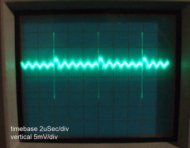
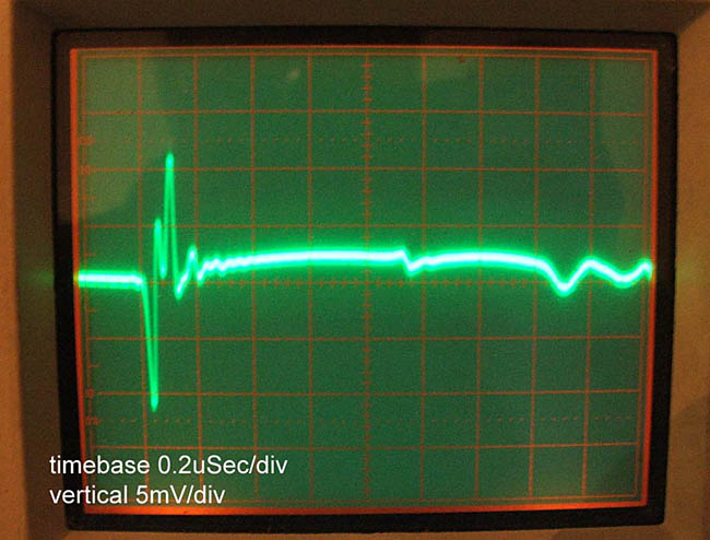
Here we'll look at using a 'gyrator' or 'capacitance multiplier' as a cheap 'n' easy filter for this noise; it's an excellent idea, since basically it's a synthesized inductor, and it behaves like an impractically-large value inductor at that. First, here's an example of crud on the output of a 24v laptop switched-mode power brick (sorry for the lousy shots); switching frequency is 50Khz:
Here's the close up - little basic ripple, but 50mV of HF spike that will pass right through most basic regulators:
Now to make the point: here's a very quickly knocked-up jig with two popular noise-killers:
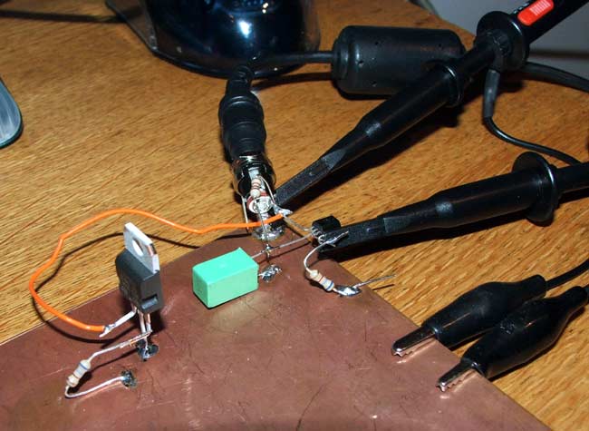
In the red corner, weighing-in at 10K//3.3uF, a transistor (BC 547B, hfe about 200) configured as a gyrator, with a 680ohm output load. In the Blue corner, a plain-jane L7812CV 3-pin voltage regulator, also loaded with 680R. Input (top of picture) is 24V from the laptop SMPS above. Note there are no bypass caps; I want to look solely at the intrinsic rejection these two methods offer, and the load is DC only. Probes go off to my old Tek475A scope... and are placed to show input and output waveforms (i.e AC components only). The input shows as the upper trace in all shots, and the vertical /timebase scales are the same unless noted. Starting point - lots of harmonics out toward 1Mhz, repetition rate 50Khz, noise 50mV Pk-Pk, complex waveform.
First up: the gyrator, or capacitance multiplier, or whatever you want to call it:
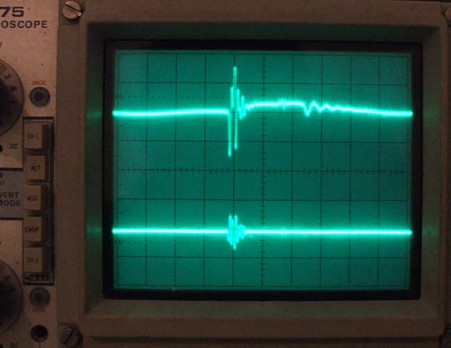
Output - quiet! Remember the basic ripple is at 50Khz, so it will be very much attenuated by the gyrator which has a corner frequency of about 5Hz. Upping the gain on the lower trace to 2mV/division only shows this rather small blip:
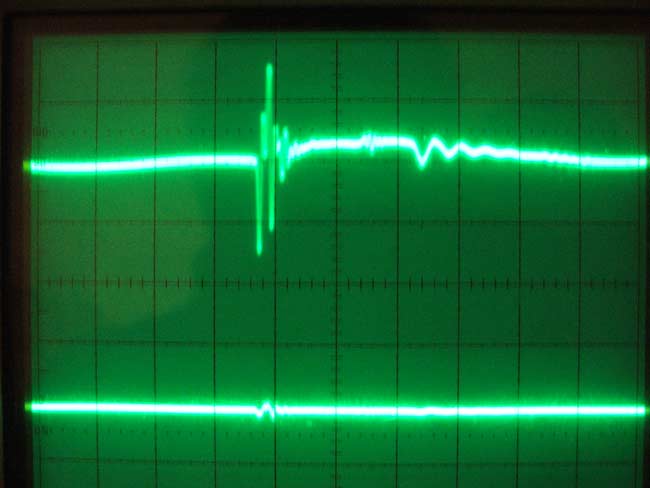
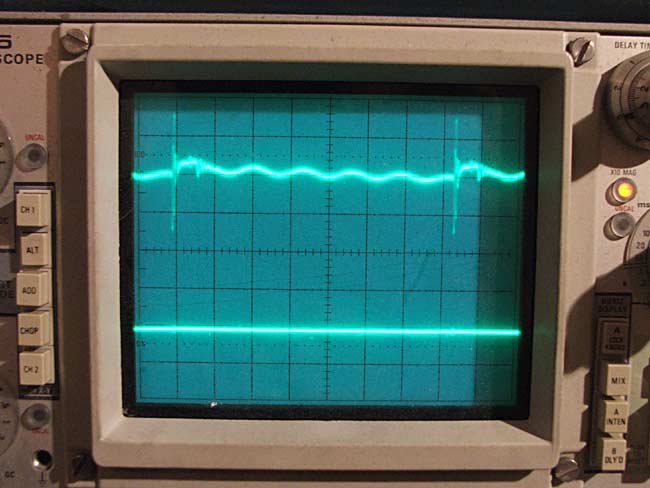
- which amounts to less than 0.2mV pk-pk. In other words, even this crudely-assembled jig maintains over 55dB rejection out past 1Mhz. Now for the 7812, with both traces at the same scale (and the same as the picture fourth from top). See? Not much rejection at all; the LF ripple is well suppressed, but all the faster stuff comes through - including a very fast, feint edge I couldn't catch with my camera.
So how much rejection do you get from a three terminal reg much above 100Khz? Maybe10dB. Think about that before you use one for something you care about, or which may have stability problems with HF noise.
And that's why the PFM Flea is prefaced with a simple BC547 based gyrator...
© 2006 the twisted pair